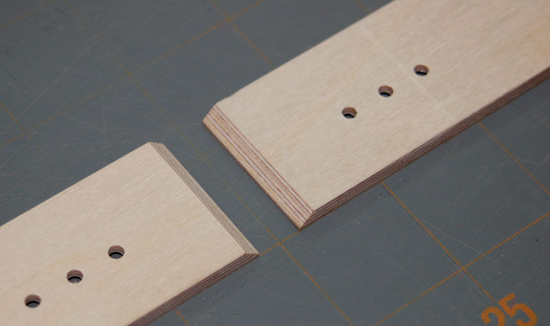
I laminated three layers of 1/16" aircraft plywood together to make a 3/16" thick base and fences. The
center lamination is cross-grain to the outer laminations whose grains run parallel to the longest dimension.
This project requires a fair amount of precision for everything to line up properly. My
machinist's square
was the most valuable player.
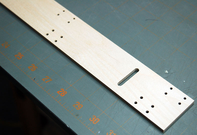
I cut out the base but didn't drill any holes in it until all the other parts were fabricated. There are two
adjustment rods for each fence half that are a close tolerance to their mating holes. They need to align very
well.
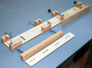
I assembled the rods, fence supports and rod clamping blocks as a unit and then attached them to the base
with permanent double stick tape.
When the parts were in place I clamped them for a couple minutes to establish a good bond with the tape. Then I
checked that everything worked properly. When I was satisfied with the operation I drilled one hole at a time
through the base into the blocks and threaded in the screw.
When all the holes were drilled I removed the screws, popped the fence assembly off the base and cleaned off the
tape.
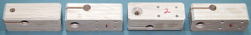
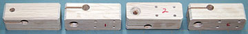
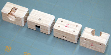
All parts are numbered so they don't get mixed up. The fences and fence
supports are also numbered so I know which end is which.
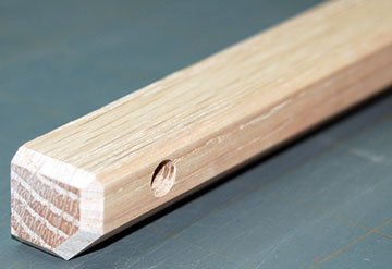 |
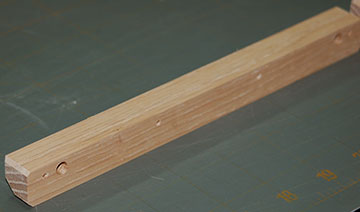
The two fence supports are machined from 3/4" square red oak. This is the back of
a fence support.
I chamfered the ends of all the blocks. Normally I round things over. I wanted to do
something different.
The chamfers are fairly large and give the fence a more rugged look.
|
 |
The front face of the fence support must be sanded dead flat
perpendicular. If it isn't then the fence will
not be flat either which will make it difficult to use the system accurately.
It might be worth it to pay a wood shop to joint the fence supports and save
you a lot of work.
If the rod supports aren't perpendicular to the face in all respects and absolutely parallel to each other then
you can bet the fences won't move smoothly and if they're off by too much the fences might not move at all!
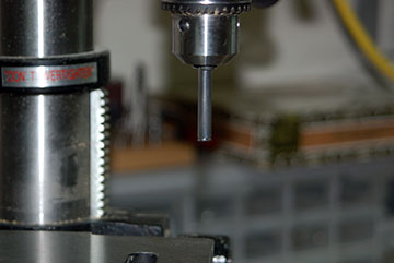
Sand the faces flat before you
drill for the adjustment rods. Drill for the rods with fence supports face down on the
drill press table.
|
 |
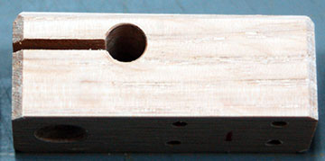
Four clamp blocks are cut from red oak. A 1/4" hole was drilled then reamed
with a 1/4" reamer to allow the fence adjustment rods to slide through easily. I used my Fox propeller
reamer which worked well.
A hole was drilled top to bottom and
tapped 8-32. The hole above the cut is drilled two sizes larger to allow it to slide over the screw when the wing nut is tightened. |
 |
After the clamp rod and clamping screw holes were drilled an opening was cut that allows the block to
clamp the rods. This clamp does not need to be tight. It only
needs to be tight enough to remove play. It's ok if the rods can
slide.
The springs and indexing bolts hold the fence in place. |
 |
The bottom of the block is countersunk to bring the 8-32 flat screw head flush. Again, all
parts are numbered because I made them accurately enough that they are interchangeable in regard to mounting them
but they aren't accurate enough to prevent binding if they get mixed up. |
 |
1/4" music wire is used to make the fence adjustment rods. I cut the rods to length.
I put
each one in my drill press and used a Dremel with an emery bit to cut groove about 1/32" from the end. A 7/32"
E-clip snaps into the groove to retain the return spring. |
 |
This wasn't as difficult to do as I imagined it would be. It took less than ten minutes to cut
grooves in all four rods. |
 |
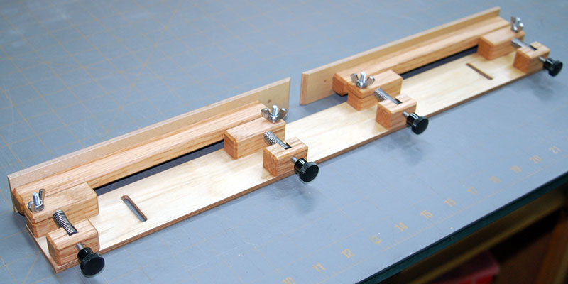
The 3/16" aircraft plywood fences are attached by four #4 x 1/2" flat head brass wood screws. The fences close to a
1/2" gap and open to a maximum of 1-3/4". |
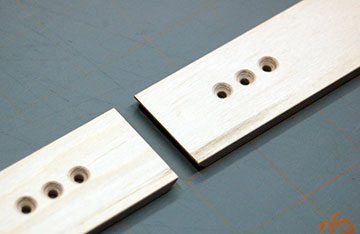 |
The mounting holes are countersunk on the front side of the fence such that the screws heads are
slightly below flush. The edges
of the holes were sanded to ensure that nothing protrudes that could catch work being moved across the
router table. |
 |
The inside edges of both fences are beveled to 45°. |
 |
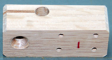
Four fence adjustment blocks are cut from 3/4" square oak. A 1/2" forstner bit was used to drill to
3/16" from the back of each block. The back was then tapped for an 8-32 bolt. It would be better if
I'd left more material for the 8-32 bolt. I chose a screw size
having thirty-two threads per inch so that adjustments don't require complex calculations.
one complete turn of the screw equals 1/32" movement. A half-turn = 1/64" and a quarter-turn = 1/128".
Each fence can adjust about 3/8" which is way more adjustment than I can imagine being necessary in any real-world
use. |
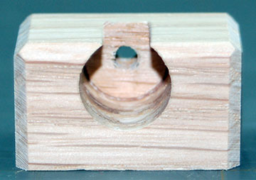 |
The front of a fence adjustment block. |
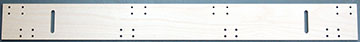 |
The base is 3/16" x 2" x 20" aircraft ply. Mine is made from three laminations of 1/16" aircraft plywood.
|
 |
Each block is attached by four #4 x 1/2" flat head brass wood screws. Two slots are cut in the
base to allow for coarse adjustment of the entire fence system. I use knobs having a 10-24 stud to mount
the fence to the router table.
Long handles will work much better than what I chose. |
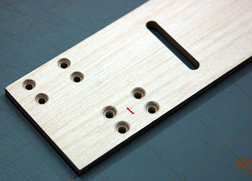 |
All holes are countersunk on the underside of the base to bring the head of the screws below flush so
they don't rub against the table. |
 |
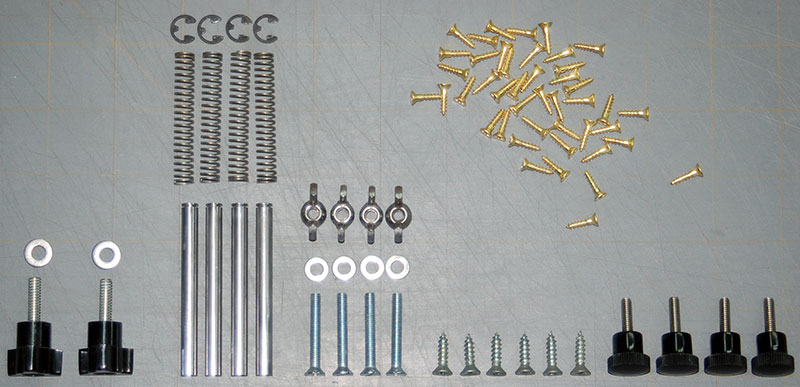
All the hardware to assemble the fence and attach it to a table. The only hardware missing are
the blind nuts that are embedded in the underside of the table. The six screws to the left of the
four black knobs aren't part of the fence system. They are used to mount the router insert into the table. |
 |
The adjustment rods are a press-fit into the fence support blocks. After the finish was applied
and rubbed out the rods were hammered in using a rubber mallet. If the rods were loose then I would use a couple set screws to
retain each rod. These are so tight that I don't have any worries about them loosening over time. If for
some reason they do loosen in the future I'll either epoxy them in place or drill and tap for set screws. Ensure
the fences are perpendicular to the table. If you were careful then they should be very close. if they
aren't then use a punch to knock the rods slightly back from the face of the fence support blocks and then sand the
blocks until they are perpendicular. When you're satisfied hammer the rods back in. |
 |
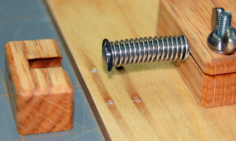
After the clamp blocks are attached, slide a return spring over the adjustment rod and then snap an E-clip in
place to retain it.
Ace Hardware has a huge assortment of springs.
I bought two different sizes because I didn't know how much force would be necessary. The sizes
I purchased were numbers 147 and 149. I don't know the number of the spring I ended up using but they're both
the same size with one being made from a larger diameter wire which is what I ended up using. The lighter
spring didn't return reliably. |
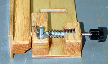 |
Bolt on the adjustment block.
The knob at the rear adjusts the fence out when the screw is turned in. When the screw is
turned out the spring pulls the fence back.
I've found that vibration from the Dremel running doesn't cause the knobs to turn and lose their settings. If
the knobs do turn on their own then I'll have to use the clamps. To adjust a fence the knob will be turned
until it makes contact with the rod before the clamp is loosened. |
 |
Clamp the assembled system to the table. Adjust both fences so they are as far to the rear as
possible. Now adjust one fence forward by turning both adjustment screws two full turns in. This will
space the fence 1/16" forward of its rear-most position. Use a good
straight-edge and align the other fence so that it is in the same plane as the first fence.
Sand the edge of a piece of scrap wood until it is straight. Slide
it along the fence in both directions and ensure it doesn't catch either fence. Adjust the fence as necessary.
Now scribe a fine centerline on top of all four knobs. These will be the indexing lines. |
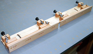
 |
Another view of the completed fence. The base and fences are finished with several brushed
coats of clear polyurethane that was sanded between coats. The last coat was rubbed with #0000 steel wool. They were then given a good coat of furniture wax
and buffed.
The oak pieces are finished with Danish oil. After the oil dried I applied a couple coats of clear polyurethane
to further seal the end grain of all the oak pieces. All these parts were also rubbed with fine steel wool. |
 |
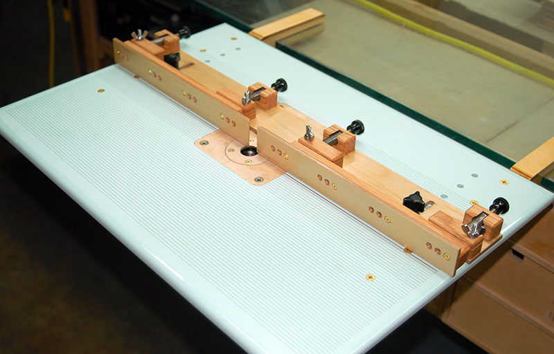
All you need is a good router table to mount the fence. |